In this article, we will discuss about Arduino programming and make some awesome projects using Arduino.
Table of Contents for this article
Arduino Software
It is not possible to program Arduino just by connecting it to the computer via USB. For this, you need to have software installed on your computer. Through this, you will be able to give programs in Arduino. Which is called Arduino IDE.
To install the software, go to the Arduino website (http://www.arduino.cc) and click on Software. Then you have to install the latest version from there.
After installing, take the shortcut to the desktop so that you can easily access it. Once the software is installed, you need to familiarize your Arduino board with your computer. That means a driver must be installed. To do this, connect the Arduino board to your computer via USB and right-click on the PC on the desktop, and go to Properties. Go to Device Manager from the left side and go to Ports, you will see USB Serial Device. If you go to it and right-click, click on Update Driver and select Browse my computer for driver software. Then go to Browse, download, and Extract it, select the Driver folder that you got, and click Next, the driver will be installed. Once the driver is installed, go to Ports and show Arduino Uno in place of the USB Serial Device, you will understand that your driver has been installed.
After installing the software and installing the driver, if you go to the Arduino software from the desktop, you will find a field for writing programs. After writing the program in it, clicking on the tick mark above will compile the program. Then when you connect Arduino to the laptop with USB and click on the arrow sign, the program will upload to Arduino. Now you can do this by opening the USB and getting power on Arduino.
Basic Things Before Moving on to Arduino Project Making
It is easy to understand the possibilities, problems, and steps of the work if you do a virtual computer before you do a project. The simulation software is used to do this virtually. So if we look at our projects first through simulation software then we can understand if it is possible or if there is a problem. For this, you can install Proteus on rice. To work with Arduino on Proteus, you need to have an Arduino driver installed. I hope you can do this from Google. Now we look at several projects on simulation software. For our next coming Arduino project, I assume you can do the work of Proteus fairly well.
LED Blinking Project Using Arduino
LED blinking means creating a project so that an LED will be on and off after a certain period. Thus a rhythm has to be created.

Circuit Diagram for LED Blinking Project
All you need to do to be a Proteus peak device is –
- Arduino.
- LED.
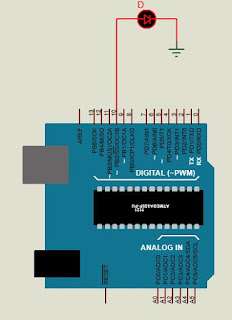
Now we connect the positive edge of the LED with pin 10 of Arduino and connect it with the negative edge like a circuit with a ground connection like this figure.
Code
In the beginning, we write the code, then it will be understood.
int led = 10;
void setup () {
pinMode (led, OUTPUT);
}
void loop ()
{
digitalWrite (led, HIGH);
}
We will first take a variable. Since we have attached the LED to PIN 10 of the Arduino, we take this pin as a variable called ‘led’. Whose value is 10. That means writing PIN 10 somewhere or writing ‘led’ is the same thing. And these variables can be of different types. Here we will take the value of the variable as 10 which is an integer type. So I have denoted this variable with int. Then we take a function called void setup (). The function of this function is to specify here – which variable or pin will work.
That is, the pin will work as input or output. Which must be written in parentheses of pinMode. Since our PIN 10 will act as the output depending on which LED is on or off, I wrote. pinMode (led, OUTPUT);. As I said before, the word led means PIN 10. Because we named it led. And in the continuous rule of programming, everyone has to give a semicolon at the end of the line.
Again we call a new function. That is a void loop (). The function of this function is to specify the function here. That is, what we have mentioned in the void setup () function, in this function they have to explain the work. Another function of this function is to follow the instructions we give in it, after the work is finished, all stops from which the work will be repeated. That is, once you follow the instructions, you will not stop, you will start that instruction again from the beginning. Until then, the previous instructions will continue. So we wrote in this function, digitalWrite (led, HIGH);. That means the positive edge of PIN 10 or led will be HIGH. And HIGH means – ON or binary number 1.
Once the code is compiled, we will get a .hex file on the C drive below. Someone must go to the Preferences from the File menu and turn on the Compile and Upload menus. Now copy the link of the hex file, double-click on the Arduino of Proteus, paste it into the Program File and click OK. Now if we run the project, we will see that the LED is on. Not extinguished. Why not go out? The answer is simple. Because we have digitalWrite (led, HIGH) in void loop () function; Wrote. This means, the LED will be on or the PIN 10 will be HIGH. LOW was not mentioned. So it will burn, not extinguish. But we intended to turn the LED on and off. Let’s do that.
This time we give the input program again as before,
int led = 10;
void setup ()
{
pinMode (led, OUTPUT);
}
void loop ()
{
digitalWrite (led, HIGH);
delay (1000);
digitalWrite (led, LOW);
delay (1000);
}
We will first take a variable. Since we have attached the LED to PIN 10 of the Arduino, we take this pin as a variable called ‘led’. Whose value is 10? That means writing PIN 10 somewhere or writing ‘led’ is the same thing. And these variables can be of different types. Here we will take the value of the variable as 10 which is an integer type. So I have denoted this variable with int.
Then we take a function called void setup (). The function of this function is to specify here – which variable or pin will work. That is, the pin will work as input or output. Which must be written in parentheses of pinMode. Since our PIN 10 will act as the output depending on which LED is on or off, I wrote. pinMode (led, OUTPUT);. As I said before, the word led means PIN 10. Because we named it led. And in the continuous rule of programming, everyone has to give a semicolon at the end of the line.
Again we call a new function. That is a void loop (). The function of this function is to specify the function here. That is, what we have mentioned in the void setup () function, in this function they have to explain the work. Another function of this function is to follow the instructions we give in it, after the work is finished, all stops from which the work will be repeated.
That is, once you follow the instructions, you will not stop, you will start that instruction again from the beginning. Until then, the previous instructions will continue. So we wrote in this function, digitalWrite (led, HIGH);. That means the positive edge of PIN 10 or led will be HIGH. And HIGH means – ON or binary number 1.
Once the code is compiled, we will get a .hex file on the C drive below. Someone must go to the Preferences from the File menu and turn on the Compile and Upload menus. Now copy the link of the hex file, double-click on the Arduino of Proteus, paste it into the Program File and click OK. Now if we run the project, we will see that the LED is on. Not extinguished.
Why not go out? The answer is simple. Because we have digitalWrite (led, HIGH) in void loop () function; Wrote. This means, the LED will be on or the PIN 10 will be HIGH. LOW was not mentioned. So it will burn, not extinguish. But we intended to turn the LED on and off. Let’s do that.
This time we give the input program again as before,
int led = 10;
void setup ()
{
pinMode (led, OUTPUT);
}
void loop ()
{
digitalWrite (led, HIGH);
delay (1000);
digitalWrite (led, LOW);
delay (1000);
}
Here we call a new function called delay (). Its function is to run or delay the instruction exactly as it is written inside this function for as many milliseconds as it is written. Then according to the code-
- digitalWrite (led, HIGH); – The LED will be on.
- delay (1000); – This is how 1000 milliseconds will run.
- digitalWrite (led, LOW); – The LED will be off.
- delay (1000); – This is how 1000 milliseconds will run.
After doing this, the program will start working from the top again according to the function of the void loop () function.
The LED will continue to be on for 1000 milliseconds or 1 second in a row.
You can increase or decrease the time of this deal if you want. But keep in mind, whatever we write inside, the delay time will be as many milliseconds.
We will discuss advanced thinking on this LED blinking project in the next part.
Advanced Arduino LED Blinking
In the previous LED blinking project, we discussed the basic LED blinking concept. Now we take this project one step further. Suppose we want to do this project with 2 LEDs. We want the first LED to light up for 1 second and the second to go out, then the second LED to turn on and the first to go out. We connected the positive end of the first LED to pin 9 of the Arduino and the positive end of the second LED to pin 10, connecting them to the negative end like a circuit with a ground connection.

Now this code is given
| int led1 = 9; int led2 = 10; void setup () { pinMode (led1, OUTPUT); pinMode (led2, OUTPUT); } void loop () { digitalWrite (led1, HIGH); digitalWrite (led2, LOW); delay (1000); digitalWrite (led1, LOW); digitalWrite (led2, HIGH); delay (1000); } |
You must have understood this program. In the same way, we can create LED blinking projects in different sequences using more LEDs.
Arduino input and output
Now we will use any one of the Arduino pins as input and take the output based on it with digital data input. And digital input means that the PIN that we will use as the input pin is either HIGH or LOW.
We are using Arduino Pin 13 as the output pin and Pin 2 as the input pin. Now let’s connect like a circuit.

Notice that if the circuit switch is on, there will be a ground connection on pin 2 of the Arduino. As a result, it will remain in the LOW state. Again, if the switch is off, the power will enter pin 2 of the Arduino through the 5V resistor. That means this pin will be in the HIGH state. Again,
If the switch is on, Arduino’s PIN number 2 will be LOW.
If switched off, Arduino’s pin number 2 will be HIGH.
Here the resistor is mainly used to resist high current.
Now we want the output to be LOW when the input pin is LOW or the switch is on or the LED is off. Again when the input pin is HIGH or the switch is off then the output is HIGH or the LED is on. For that we uploaded the following program to Arduino.
| int led = 13; int input = 2; int state; void setup () { pinMode (led, OUTPUT); pinMode (input, INPUT); } void loop() { state = digitalRead(input); digitalWrite (led, state); } |
Here we have declared a total of three variables, including a new state variable. We have used pin 13 as the led variable as the output pin and pin 2 as the input variable as the input pin.
Now a new variable is a state. Which is new to you. We are going directly to the void loop () function. Here we have used a new function in the state variable. That is, digitalRead ().
The function of this function is to read the status of any Pin B variable (whether it is HIGH or LOW). For example, digitalRead (input) will read the function here, input or pin number 2 has HIGH or LOW. If there is HIGH, then the value of the state variable will be HIGH. And if there is LOW, then the value of the state variable will be LOW. Then we have digitalWrite (led, state); Used. That is, whatever the value of the state variable will be, it will be the value of the 13-numbered pin or led variable. E.g.
If the circuit is switched off, the value of the input is HIGH. Then state = HIGH. So digitalWrite (led, HIGH); Or led pin will HIGH. That means the LED will light up. Similarly, if the switch is on, the LED will be switched off.
Thief Detecting Machine Using Arduino
Using Arduino’s above input output project we can make a person’s presence detector or a thief-catching machine. For which we need all the components-
- PIR sensor.
- Arduino board.
- Jumper connection.
- Breadboard.
- Buzzer.
Sensor Connection
The PIR sensor does not give any output when everything is stationary in front of it. But if an object with movement is present, it will give 5V output which we can also call digital HIGH. And if such an object is not present or everything in front of it is stationary, it will be in LOW state or will not give any voltage output.
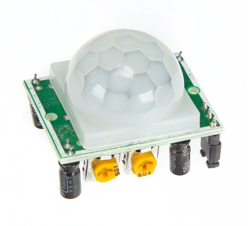
Notice that the sensor has 3 pins. Of these, we will supply 5-12V with a positive edge in VCC and a negative edge in GND. If there is nothing in front of the sensor, its OUT pin will not give any output or will remain in a LOW state. And if something moves in front of the sensor or sees any movement, the OUT pin will be in a HIGH position or give 3.3V output. With this voltage, we will play a Buzzer. Only then will our desired project be created.
Notice, the PIR sensor has two potentiometers. Whose name-
- Delay Time Adjust.
- Distance Adjust.
Delay Time Adjust: After receiving the presence of the object in front of the sensor, the length of the OUT pin will be HIGH or the Buzzer will play, and the potentiometer is turned to fix it. This can be done from 1 second to 5 minutes.
Distance Adjust:The limit of how far the sensor will be kept under observation is adjusted by turning it.
Now we want the Buzzer to play when the OUT pin of the sensor is in HIGH state, and when it is in LOW state, the market will stop. For the project, we connect like before the circuit.

Now Notice,
Arduino uses two GND pins, one with the negative edge of the BUZZER, and the other with the GND pin of the sensor. This pin is then connected to the Arduino’s 5V Power pin to power the VCC pin of the PIR sensor from the Arduino board. Now the main thing is that we have connected the OUT pin of the PIR sensor to the 5th pin of Arduino, and the positive end of the BUZZER to the 2nd pin of Arduino.
So our job will be when the OUT pin of the Buzzer or the 5th pin of Arduino will be in HIGH state, then the positive edge of the Buzzer or the 2nd pin of Arduino will be in HIGH state. Again when the OUT pin of the Buzzer or the 5th pin of Arduino will be in LOW state, the positive edge of the Buzzer or the 2nd pin of Arduino will be in LOW state. And if the Buzzer has a positive pin HIGH, the Buzzer will ring. Then we upload the following code to Arduino.
| int buzzer = 2; int pir = 5; int state; void setup () { pinMode (buzzer, OUTPUT); pinMode (pir, INPUT); } void loop() { state = digitalRead(pir); digitalWrite (buzzer, state); } |
According to the previous project, the code must be understood, whenever the PIR sensor will output or HIGH, the Buzzer will be HIGH. That means the Buzzer will ring. You can also use LED instead of a buzzer if you want.

Leave a comment